
Auto Design – Designing Adaptive And Fixed Roads
This topic outlines general guidelines for configuring road definitions for your automated design project in your application.
Being aware of how your application projects a pit (top-down or bottom-up) may help you resolve situations where design strings generated by the Auto Design task are unexpected, or do not fully display in the projected pit and integrated roads.
General Approach
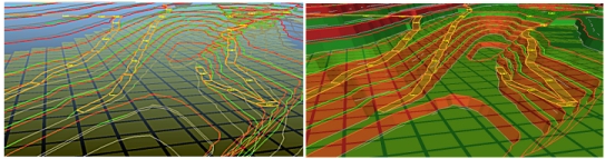
Your application attempts to integrate a road into your pit or dump design by constructing inside and outside berms so that a road of the predefined width can progress at the given gradient between toe and crest bench elevations.
The road does not exceed the gradient specified in the Auto Design task, but is adjusted where appropriate to raise or lower the ramp as smoothly as possible while maintaining the expected pit wall tapering at the start and end of each segment.
Your pit or dump face is modified with the introduction of roads.
As a reminder of how a road is constructed manually in your application:
- Select a start point.
- Enter a starting azimuth, gradient, turning radius and (possibly) a limit to the turning curve.
- Define the ramp string distance and final azimuth value.
- Create a road berm by specifying a width and start and end taper distance.
- Repeat for every bench or lift, either upwards (bottom-up) or downwards (top-down).
Note: A more detailed explanation can be found here.
Your application attempts to do this automatically for each bench or lift, and takes into account all of the parameters required for pit design to avoid violation of constraints.
Tip: It can be clearer to hide the Design Surface before you create a ramp, and design the ramp with reference to the existing design strings. This prevents the fixed road centreline from being obscured by surface data.
A road is integrated, providing:
- Consider using scenarios to test the viability of parameter changes; you can Clone a scenario and edit one or more parameters to assess the impact on the resulting design and, if you are generating them, volume evaluations.
- A road definition exists, either constructed using the Ramp Layout tool (pits only) or the Auto Design task.
-
The road start point can be determined within the projected pit or dump, based on the above definition.
Note that the start point is the only part of a road definition that is determined by an absolute XYZ value, so if it is a huge distance from the initial constraint string or perimeter, it may not be possible to start the road design. For pit designs, this is why Ramp Layout is useful; you create your road definition using a phase DTM as a canvas. The same DTM is used to define contour strings, which in turn are used to define one or more constraint strings for your pit. This facility is not available for designing dumps. - The road can be logically integrated within the pit while adhering to the designated slope region (face angle and berm width) settings for the pit. Face angles and berm widths are non-negotiable.
- The road width can be accommodated.
- An extreme change of direction, such as a dog-leg or crevasse, does not cause the road to end prematurely.
- The road gradient is not violated (that is, exceeded) by integrating the road.
- Road turning radii can be managed, including any additional conditioning and or berm tapering options that have been set.
- Switchbacks can be inserted without violating slope region parameters.
- The road end elevation or uppermost or lowermost bench crest or toe can be reached: there is no flat surface (zero gradient plateau) along the way.
- A valid constraint string at the current elevation can still be integrated into the design. If not, the constraint is used and the road is terminated early.
-
If you are designing a fixed road, the second point defines the direction of the initial 2-point ramp (which can be modified afterwards).
If you are viewing your data in anything other than a section-aligned view, the resulting string may not lie directly beneath your cursor because the direction is defined on the current section plane.
The resulting string rises from that plane, and away from the cursor if the view is not orthogonal to the section.
It is recommended that initial ramp design is performed after aligning the view with the section (View ribbon View >> Align).
Road integration is performed while attempting to honour any constraint strings that have been specified, providing these do not violate slope region settings.
Where possible, your design is adjusted to ensure road integration is successful. This is done by either pushing out the pit wall or pushing in the dump wall where required to build a road into the design.
Pits are not pulled inwards as this may violate slope region settings and operational or safety requirements.
Tip: You can change the colour of your toe, crest and ramp strings (and other items) using the Advanced Settings tab.
The algorithm used to integrate road strings within an automatic pit design is complex and, while every effort has been made to manage edge scenarios and convoluted geometry, there may be situations where the results you have created are, at first glance, unexpected.
Adding Fixed Roads To Your Design
Just like adaptive roads (see above), fixed roads are defined using a start point and a gradient, but a Fixed Road differs in that it is not constrained to the pit or dump wall.
In some ways, a fixed road centreline behaves like a constraint string in that, whilst an adaptive road will maintain the overall shape of the pit (with minor modifications to crest, toe and berm strings), a fixed road will actively reshape the pit to accommodate itself, creating a "box cut" as required to ensure the specified gradient is honoured. Just like adaptive roads, the gradient is non-negotiable, as is the face angle(s) and berm/catch berm widths.
Fixed roads are defined using a start point, then a string (of any shape) to design the ramp. A box cut will be performed where needed, as will embankments.
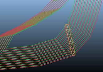
Consider the pit design example below: the left-hand image shows a road insert from bench 0 to 100m (the first bench) and the right-hand image shows a fixed road:
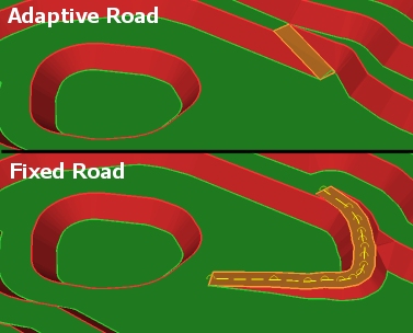
The same principle applies to dump designs.
The fixed road design will automatically shape the necessary raises/embankments and box cuts, modifying all benches above it to the pit or dump rim in order to insert it.
As the gradient of a fixed road is preserved and the design will always be updated to achieve it and the slope region settings. As such, defining the start point of a fixed road and a direction will cause the new road to be continued in the direction indicated by the string until it reaches the target elevation. The variable will be the distance over which the fixed road is progressed.
Adding a fixed road is as simple as defining a string (2 or more points, open and without crossovers), reviewing it and optionally conditioning it, then using Recalculate to insert it into the current design.
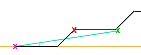
For example, in the image below (showing a cross-section of the lower benches of a pit), a simple 2-point string is used to define a fixed road start position (X) and a right-click (X) is used to define the final elevation. As the gradient is sacred, the fixed road will actually box-cut into the pit to terminate at X, with all benches modified to ensure the design does not violate gradient, slope region or other string-based constraints.
In this example, a 3D view of the result could look like this:
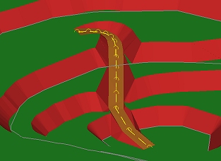
Note how pit material is both excavated (box cut) and added (embankment) to ensure the gradient and other constraints are honoured.
Fixed roads can be multi-point strings. In fact, they can be any open string without crossovers and you can use any of Studio's string editing commands to prepare them ready for design string calculation.
The Move Fixed Road command is particularly useful as it allows you to move the fixed road in its current plane anywhere in the pit or dump. You can also rotate the fixed road centreline string with this command. Insert Line and Insert Curve commands are also powerful here. Remember to Recalculate to see the change in design strings.
Fixed roads can be used for either pit or dump design projects:
Fixed road centrelines may be edited using any of Studio’s string editing commands, not just those provided in the Task. After each edit, the edited fixed road centreline will have its end elevations automatically snapped to the nearest bench elevation, and intermediate point elevations will be auto-corrected to ensure a constant gradient along the centreline. The resulting gradient is written back as an attribute on the string (GRADDEG, GRADPER, GRADRAT), so the Data Properties bar can be used to see the results of any editing on the current road gradient.
Fixed roads can only be defined using either of the pit or dump Auto Design tasks; due to the modifications required to accommodate fixed road designs (they only make sense in the context of the surrounding constrained toe, crest and berms, so there is no provision for fixed road design in the Ramp Layout task).
You can show or hide the display of fixed road centrelines using Show Fixed Road Centrelines.
Where a fixed road cannot be created for any reason (say, it violates a non-negotiable constraint such as face angle or berm width), a message will be output to the Output window.
Here are some tips for designing fixed roads (some also apply to adaptive road designs):
-
Use the Bench Clipping toolbar to set the elevation of the bench on which the first point of a fixed road sits.
This makes it easier to select any position at that elevation using a left-mouse click to start your fixed road.
You can then use the Bench Clipping toolbar again to set the elevation of the second point.
This approach helps ensure your start and end points are at the expected elevation. - Use snapping, but make sure your snap settings are set correctly before you begin. Use the Home ribbon to ensure string and point snapping are enabled. You can then use right-clicking to define both start and end positions and use an existing crest or toe string to force each point to a given elevation. As the move-points-mode command modifies these points without adjusting their elevation, you can use a combination of snapping and moving points to get the effect you want.
- The gradient is honoured, but you can still force an over-gradient string by manually editing start and or end positions. Be careful you do not design a ramp that cannot be used by your machinery. Any edits change the gradient; for example, adding more points changes the length between the previous elevations. However, a constant gradient is then calculated and reported in the attributes.
- Insert-curve and insert-line are an easy way to condition your fixed road centreline strings. Insert-line, for example, can be used to digitise around a known obstacle.
- If your fixed road terminates at a bench or lift and there is not sufficient space at the top to accommodate your haulage equipment, add a constraint string to push the face back, away from the ramp exit.
- Fixed road strings are effective if you want to control the gradient of a ramp coming out of the pit or dump. In a bottom-up design, set your start point at the required in-pit bench, then left-click in the ramp direction to ensure the gradient is honoured on exiting the pit. The remaining benches are modified to accommodate the ramp up to the pit rim.
- Fixed road strings are stored in a temporary object. This object is always suffixed with "...TRNCHCEN" and can be accessed in the Sheets control bar. You can change the format of this string (colour, line style, and so on) if you want, and this format is maintained throughout the current command session. You may want to highlight the fixed road centreline vertices.
- If you find your fixed road string is either partly or fully disconnected from the other design strings, you can snap the string back to a more sensible position using the Move Points command in combination with snapping.
- Use the Offset road ends and Kink correction settings in combination with berm taper widths to control how adaptive road segments are placed up or down the pit.
- Consider enabling and disabling roads to see how road design impacts the surrounding pit shell shaping.
Design Feedback – Using The Output Window
Your application uses the Output window to provide feedback about events triggered during your auto-design.
Various message types are available. Some indicate where an alternative or modified parameter has been used to maintain the integrity of your design, while others indicate that it was not possible to start, progress, or complete a road design within the current pit phase.
If everything has worked successfully, you see nothing in the Output window. Otherwise, information is shown in the following formats:
| Message Type | Cause | Potential Solution |
|
Road Error: #Road Name# crosses the starting elevation of nn and has had its road start point temporarily moved there... |
The road start point is either below the lowest pit or dump constraint string (bottom-up design) or above the uppermost constraint string (top-down design). For pit designs, a common cause is using the Ramp Layout tool to get a rough definition for your in-pit haulage, designing directly onto the phase DTM, and the start point is below the first constraint string (for example, the lowest generated contour). |
Unless the road position is unexpected, you can ignore this message, or use Move Start and right-click to a point on or above the initial constraint string. This resets the road start position to the elevation of the constraint string and Auto Design no longer has to modify the definition when calculating design strings. |
|
Road Error: #Road Name# could not find a profile between elevations nn->nn |
It is not possible to construct a road between the specified elevations. This indicates the road could not find its way up or down a temporarily triangulated surface between contours. Auto Design tasks use temporary surfacing to generate road contours and strings. Potential causes include a sharp direction change in a projected crest or toe string, or a constraint string or switchback requiring a shape that cannot be generated while honouring road definition settings (width, taper, gradient, conditioning). This error causes the road to stop at the previous bench and not reach its target elevation. |
If this results from a switchback, consider moving it away from dog-legs or severe changes of contour string azimuth. Smooth the contour or constraint string at the road start position using standard string editing tools. Removing points in a congested area can reduce extreme directional changes. Consider adjusting the gradient of impacted road segments so a problematic area can be avoided. Edit Gradient can be effective in these situations. |
|
Road Error: #Road Name# cannot find road exit and entry points on offset profile between elevations nn->nn. Road Error: #Road Name# cannot find road end points on cleaned profile between elevations nn->nn. |
Both errors result from a failure to define a road segment from the expected profile. These issues are usually caused where the road finishes very close to a corner in the contour string. This can cause the road to fold back on itself to the extent that the expected corners at the road exit can no longer be found. |
The following methods can help resolve these errors:
|
|
Problem with inside or outside radius filleting on crest contour at elevation nn. No inside or outside radius filleting has been used. |
It has not been possible to apply the current inside or outside filleting parameters (as defined by the Conditioning tab). This can be due to azimuth changes in the contour strings on which the road design is based; a tight corner does not permit the inside radius (bottom-up) or outside radius (top-down) to fit while maintaining road width, gradient, or other conditioning factors. Another possible cause is an internal filleting radius that is so large it causes the contour to be removed. The end result is that road exit points can no longer be calculated, so filleting has been removed from the affected road segment(s). |
Adjust filleting options per bench using the Conditioning tab, then regenerate design strings. Alternatively, remove the filleting radius by changing the affected bench or lift value(s) from "-" to "0". You can also recreate or refine constraint strings to remove severe angle changes. This reduces the likelihood of trying to squeeze a turning radius into an impossibly tight corner. |
|
Road [name] has a zero or negative width and has been ignored. |
A fixed road cannot be formed because other constraints force it to assume a zero width or a crossover (negative width). |
Adjust filleting options per bench using the Conditioning tab and regenerate design strings. Alternatively, remove the filleting radius by changing the affected bench value(s) from "-" to "0". You can also recreate or refine constraint strings to remove severe angle changes. This reduces the likelihood of trying to squeeze a ramp into an impossibly tight corner. |
|
A road centreline was found with no name and has been automatically labelled as [new name]. |
It has not been possible to match a fixed road centreline with a name in the current project. An automatic name is assigned. |
No action required. |
|
Duplicate road name. Road [old name] has been renamed [new name]. |
A fixed road name matches an existing road name and has to be renamed to a unique reference. |
No action required. |
Related topics and activities